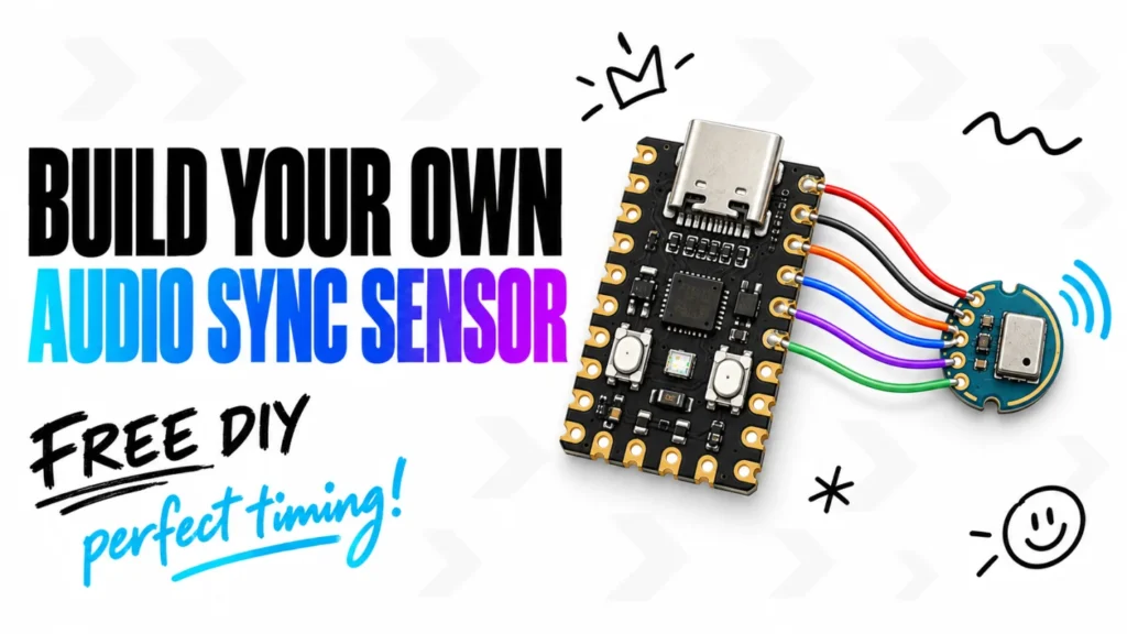
Two small boards, six wires, and a USB cable. That is the hardware behind this DIY version of the LTEK Audio Sync Sensor. If you are comfortable soldering a few labeled connections, you can build the same RP2040-Zero and INMP441 setup used in our StepMania LTEK tests.
Build Your Own LTEK Audio Sync Sensor
The sensor helps StepMania measure how long sound takes to reach your playing position. The game plays a sequence of test sounds, the sensor detects them, and the game calculates an audio timing correction. It calibrates audio, not video. You still adjust display timing separately.
The sensor works with StepMania 5 LTEK Edition, the free Windows beta you can get from our software page. Both downloads used in this guide, the firmware image and the wiring schematic, are kept on that page too.
Build the tested version. This guide keeps the existing hardware, wiring, and firmware unchanged. Use a Waveshare RP2040-Zero and an INMP441 I²S microphone module with an open acoustic port. The firmware download below is the exact reference image used in our two working test sensors, not a new experimental build.
Prefer a ready-made sensor? LTEK is also developing a fully assembled version of the LTEK Audio Sync Sensor, expected to be available soon at iAmats.com. This DIY guide is for anyone who would rather build their own. Pricing and the release date have not been announced yet.
What to buy in the U.S.
| Part | What to look for | Quantity |
|---|---|---|
| Controller | Waveshare RP2040-Zero with USB-C and BOOT/RESET buttons | 1 |
| Microphone | INMP441 I²S breakout, with VDD, GND, SCK, WS, SD, and L/R connections | 1 |
| Wire | Thin insulated hookup wire, about 2–4 inches per connection | 6 pieces |
| USB cable | A USB data cable, not a charging-only cable | 1 |
| Enclosure | Nonconductive, with an opening for sound and strain relief for the cable | Optional |
You will also need a fine-tip soldering iron, solder, flux, and a multimeter. Buy a complete microphone breakout board, not a bare MEMS chip that requires surface-mount assembly.
Amazon, local electronics stores, or AliExpress
Pick the shopping route that works for you. Amazon.com is a convenient place to compare sellers and delivery dates. A local electronics or maker store lets you ask about the exact module and, when buying in person, inspect the microphone opening. AliExpress is another option if you can allow time for shipping and check the seller’s photos carefully.
| Where to shop | RP2040-Zero | INMP441 microphone |
|---|---|---|
| Amazon.com | Find Waveshare RP2040-Zero | Find INMP441 I²S modules |
| U.S. electronics suppliers | RobotShop U.S. storefront | Vetco Electronics or ShillehTek |
| AliExpress | Find Waveshare RP2040-Zero | Find INMP441 I²S modules |
The Amazon and AliExpress links open search results, not a specific LTEK-approved listing. Choose the exact parts described below, not whichever similar-looking board appears first. Check the seller, shipping origin, delivery estimate, return policy, and photos of both sides. A marketplace name or a “compatible” label does not guarantee the correct microphone or an open sound port. AliExpress orders may ship internationally; set your destination to the United States before comparing delivery options.
Waveshare RP2040-Zero
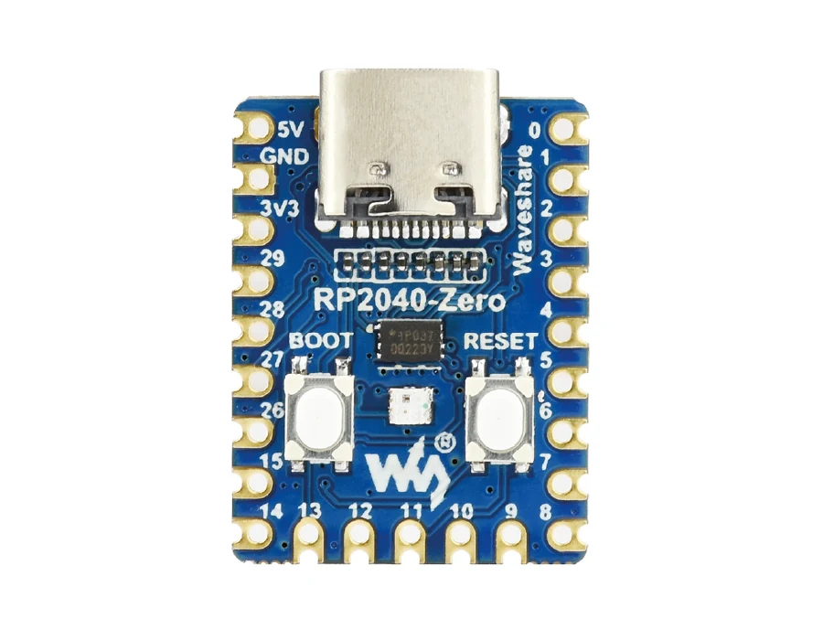
Look for the Waveshare RP2040-Zero without headers, manufacturer part 20187, on Amazon, AliExpress, or at an electronics supplier. For a specific supplier listing, RobotShop’s U.S. storefront carries it as SKU RB-Wav-359. The version without headers is convenient for soldering short wires directly to the board. Confirm stock, shipping origin, and delivery time at checkout; a U.S. storefront alone does not guarantee domestic warehouse fulfillment.
Use the Waveshare product documentation to identify the board. Do not substitute a Raspberry Pi Zero, RP2040-PiZero, Pico 2, or a similar-looking controller. A full-size Raspberry Pi Pico is not a drop-in replacement for this build: GP29 is not exposed on its standard headers, and its LED arrangement differs. This download is for RP2040-Zero only.
INMP441 microphone module
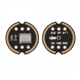
ShillehTek sells an INMP441 I²S microphone module with U.S. fulfillment. Its listing explicitly states “Ships from USA.” Another U.S. shopping option is Vetco’s INMP441 module, SKU TEA-7491. Check current stock and shipping details before ordering.
These are purchasing leads, not a claim that LTEK has tested every seller’s current batch. Ask for clear photos of both sides and confirmation of the microphone part if the listing is ambiguous. We need an INMP441 with digital I²S output, not an analog sound detector, PDM microphone, or an unspecified “compatible” replacement. Board color is not a reliable identifier.
The tiny hole matters more than it looks
Before buying, inspect the underside of the microphone board. There must be a visible, unobstructed acoustic opening directly under the microphone’s sound port, typically near the center of this style of breakout. A solder-filled via, solid PCB, glue, or tape is not an acceptable substitute for that opening. Blocked boards can be far less sensitive and may fail to detect the calibration sounds.
The INMP441 is a bottom-port microphone: sound enters from underneath the metal package. That is why the breakout board needs a clear path through the PCB. See the TDK INMP441 datasheet for the package and acoustic port. The larger holes around the edge are electrical connections, not the microphone inlet.
If you cannot see the sound opening, ask the seller before you order. If your board arrives with it blocked, replace it. Do not drill through a board with the microphone installed or poke a needle into the port: dust, metal shavings, and pressure can damage the MEMS element. Do not cover the opening when mounting the board in a case. A clear port is necessary, but it does not by itself prove that a module is genuine or working correctly.
Download the firmware
The same firmware used in our working sensors
Download LTEK Audio Sync Sensor firmware (.uf2)
Hardware: RP2040-Zero + INMP441, wired exactly as shown below.
Build identifier: reference-original45s, unchanged binary used in both working sensors.
SHA-256:2c992bb490e6634698a88513bac9ebc97d73617fb57b74c311fa36d18c30f1f2
This is the reference firmware used with the current LTEK beta. It is not a claim of certified absolute timing accuracy or compatibility with every microphone module. The public source-code package and its licensing information will be linked separately when available.
Start with the RP2040-Zero by itself, before connecting the microphone. Hold BOOT, plug the board into your computer, and release the button. A drive named RPI-RP2 should appear. Copy the downloaded .uf2 file onto it. The board restarts and the drive disappears; that is normal. Then unplug USB before soldering anything. Waveshare documents this loading method in its RP2040-Zero guide.
No drive? Try a known-good USB data cable and another USB port. Never copy this file onto a board that controls a dance pad, relay tester, or another device. Use a dedicated RP2040-Zero for the sensor.
Connect the boards with six wires
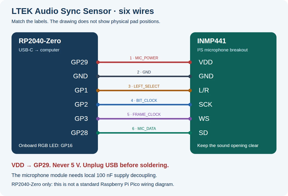
This is a logical wiring diagram, not the physical arrangement of pads on every module. Follow the printed labels on your boards. GP means GPIO number, not the position of a pin.
| RP2040-Zero pad | INMP441 pad | Purpose |
|---|---|---|
| GP29 | VDD or VCC | Firmware-controlled microphone power |
| GND | GND | Common ground |
| GP1 | L/R | Left-channel selection controlled by firmware |
| GP2 | SCK or BCLK | Bit clock |
| GP3 | WS, LRCLK, or LRCL | Frame clock |
| GP28 | SD or DOUT | Microphone data to the processor |
Never connect microphone VDD to 5 V. In this tested design, VDD connects to GP29, not GP0, VBUS, or the always-on 3V3 pad. Do not tie GP29 to 3V3. The firmware switches microphone power on only for a measurement.
This GPIO-powered arrangement is for one simple, low-power INMP441 module, without an added amplifier or lighting. Do not power additional devices from that pin. The module should already include local power-supply decoupling; TDK specifies a 0.1 µF (100 nF) capacitor between VDD and GND close to the microphone. Do not add a large capacitor to this GPIO-powered circuit as a guesswork fix. TDK power-supply recommendations.
Solder one wire at a time with USB disconnected. Keep the wires short and avoid heating the microphone’s metal package. Insulate exposed connections without blocking the sound inlet. If a child is helping, an adult should handle soldering.
Download the EAGLE wiring schematic (.sch)
This file describes connections between two ready-made modules, not a PCB manufacturing design. Symbols are embedded. Its XML and six connections have been checked; opening it and running ERC in EAGLE still require verification.
Check your work before plugging it in
With USB disconnected, check each wire against the table. Use your multimeter to check continuity and look for shorts between neighboring pads, especially power and ground. Do not measure resistance on a powered circuit. If either board gets noticeably hot after connection, unplug it immediately and inspect the assembly.
A small plastic enclosure protects the boards from metal surfaces and accidental shorts. Leave the microphone opening clear, keep the LED visible, and secure the USB cable so a pull cannot rip out the wiring.
Run your first audio calibration
Connect the finished sensor to a computer running a compatible StepMania LTEK beta. Open Options → Audio & Video Sync → Use LTEK Audio Sync Sensor. Without the sensor, the automatic option stays visible but disabled; manual calibration remains available.
Place the sensor near where your ears will be when you play. Use a comfortable, normal playing volume and turn off other sounds for the first run. The game starts the listening session automatically. You do not need to hold BOOT for calibration; BOOT is for loading firmware.
Let the game test its signal level and complete the measurement. Review the result and preview before choosing Save and finish, which saves the settings and returns to the main menu. The sensor does not adjust video timing on its own.
Repeat the measurement two or three times without changing the sensor position, volume, or audio output. Results should be similar. If they vary substantially, check the acoustic opening, wiring, microphone quality, and audio setup instead of choosing whichever number looks best. Recalibrate after changing your TV, speakers, or audio connection. A fixed offset cannot eliminate continuously changing Bluetooth latency.
Troubleshooting
| What you see | What to check |
|---|---|
| No RPI-RP2 drive | Hold BOOT while connecting; try another data cable and USB port |
| The game does not recognize the sensor | Correct firmware, RP2040-Zero board, compatible game version, then reconnect USB |
| Very weak response or missed sounds | Inspect the underside sound opening first; check the case, module quality, and normal listening volume |
| No response at all | VDD to GP29, SD to GP28, L/R to GP1, common ground, and GP2/GP3 not swapped |
| LED flashes but calibration fails | A flash is not proof of a valid timing sample; check the game’s result and reduce background noise |
| Results change from run to run | Keep position and audio settings fixed; investigate variable audio latency or a faulty microphone |
A note about privacy
The supplied firmware reports detected events and timestamps rather than streaming audio recordings to the game. It switches microphone power for measurement sessions. That is a property of this firmware, not a hardware guarantee against a different program: a MEMS microphone can detect speech, and modified RP2040 software could use it differently. Install firmware you trust, and unplug the sensor when you do not need it.
The goal is straightforward: a small, repeatable build that makes it easier to get your music and your steps in sync. Choose the right module, keep its sound opening clear, and follow the six connections exactly.
Once the sensor measures your setup, the rest happens inside the game. The New StepMania LTEK Edition walks through what else the beta adds, and the software page has the installer.